First Arduino Lesson For Children: Lesson 1 – Blink Led 13

Today, I gave my first Arduino lesson to my sons (ages 8 and 12) and their friend (age 13).  It only covered identifying parts of the arduino board, hooking the arduino to the computer, starting the IDE, using the built in blink example, changing the example to flash S.O.S. in Morse Code, refactoring the example so that it uses a “dot” and a “dash” function, and then writing something else in Morse Code of their choice.

The lesson print out is below, but let me give some insight into how it went.

My younger son (8 years) had some trouble with putting the “delay” command between the digitalWrite(13, HIGH) and digitalWrite(13, LOW).  Delaying while the light is off made sense to him, but using it to keep the light on was counter intuitive and difficult for him to grasp.  I need to find a good way to explain it.

My older son (12 years) had no trouble with creating the basic function.  The only mistake that he had trouble with was putting the code in between () for the dot and dash functions he defined.  I explained this and he was on his way.  He even created a function for each letter so that he could just spell out the words using function calls like this for “hi”:

h();

i();

My son’s friend (13 years) had no trouble.  He was able to do the morse code with no trouble. 

I think all in all, this lesson would work out best for 6 grade and above..

—-Lesson 1—–

Arduino Lesson 1 – Blinking LED 13

Learning Objectives:

· How to hookup the Arduino to the computer

· How to open the Arduino IDE

· How to type a simple program into the Arduino IDE that blinks the built in light on the board

· Learn the basic syntax and structure of an Arduino program (Arduino programs are called sketchs)

· Learn the commands pinMode, digitWrite, delay

· Learn how to define a function

What you will need:

· Computer

· USB cable

· Arduino Duemilanove Board

· Arduino software (assumed to already be installed on the computer)

Activity 1: Take a look at the Arduino board

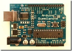
clip_image002

Try to identify the following items:

· Digital pins 0-13

· GND pins (how many of them are there?)

· 5V

· 3V

· Analog In 0-5

· Pins marked PWM

· Pins marked “TX” and “RX”

· Pin marked Reset

· Pin marked Aref

· USB connection

· Power connection

· ICSP pins

· Reset-EN label

· Reset button

· Lights marked “L”, TX, RX, PWR

What do the following terms mean:

Digital

Analog

GND

5V

3V

PWM

TX

RX

Reset

(aref we will learn about later)

Activity 2: Connect the Arduino to the computer using the USB cable. Which lights come on? What do you think that means?

Activity 3: Open up the Arduino IDE. Go to the “file” menu, choose “examples”, then “basic”, then “blink”

Take a moment to look at this program. This is written in a computer language called “C”. There are several things that you should know about “C”

1. It is case sensitive. So “hello” is different than “Hello”. (notice the first one has a lower case ‘h’ and the second one has a upper case ‘H’)

2. Every statement must end with a semicolon “;”. What is a statement? A statement is a command that you give to the computer. Look at every line that ends with “;” to see examples of statements

3. function are commands that are built in and that you can define yourself. There are two functions that are defined here: setup and loop. These are very special to the arduino. When defining a function you have to specify if the function will “return” a value. Since these do not return a value, you see that “void” is listed before their names. Do not worry about understanding this now. It will make more sense later.

4. After the function name is defined there is a set of () with nothing in them. This is where the parameters of the function will go. “setup” and “loop” do not take parameters so they are blank. Again, do not worry about understanding it now. It will make more sense later.

5. The actual code of the function is contained within in braces: {}

The “setup” function gets called one time.

The “loop” function gets called over and over and over again.

Take a look at this program. Can you figure out what it does?

In the setup function there is a statement: pinMode(13, OUTPUT); This set the Digital Pin 13 to be in Output mode. This means we will be sending a value to this pin. You could specify INPUT which would mean that you would want to “read” a value from this pin. This we will do when we get to buttons.

In the loop, there are two functions used: digitalWrite and delay. digitalWrite will turn “on” the pin when it is “HIGH” and turn “off” the pin when it is “LOW”. delay will wait the specified number of milliseconds before the program continues.

How many milliseconds are in a second?

How about in 10 seconds?

How about in a minutes?

Activity 4: Upload the sketch to the arduino and see what happens. Do this by click “file” and then “upload to I/O board”.

Notice which lights blink as it is uploaded. Then what happens. Does it do what you thought it would?

Click the “reset” button. Now what happens?

Activity 5: Blink S.O.S in Morse Code.

SOS is dot dot dot dash dash dash dot dot dot wait and then repeat it again.

Dots mean that the light is on for a short time, and dots mean the light is on for a long time. How can you modify this program to make the lights blink this way?

Activity 6: Use a function to make our code nicer.

See how we use the digitalWrite(13,High), delay(…), digitaWrite(13, LOW), delay(…) over and over again for the dash and the dot. And in our code it is difficult to make out where the dots are and where the dashes are.

Let’s make our code easier to read by defining two functions, and then using them.

Define one function called dot like this:

void dot() {

…. Put the code here to make a ‘dot’

}

And one for dash like this:

void dash(){

… put the code for a dash here

}

Now our loop function should read

void loop() {

dot();

dot();

dot();

dash();

dash();

dash();

dot();

dot();

dot();

}

Notices how the dots all blend together? How can we fix that?
Control LEDs over the wireless network using Arduino and WiShield

The Arduino microprocessor is a very affordable embedded systems solution.  It costs about $20 per unit, and can be program easily in C.  It has easy access to digital input and output pins, as well as analog input pins.  In combination with the WiShield it allows for you to control lights, motors, and more over the network as well as monitor temperature, humidity, noise, etc. 

This video provides a basic demonstration of controlling three LED lights over the wifi network at my home via a web browser on the iPhone.  This provides the very basics of what you need to get started with the WiShield and controlling things over the wireless network. 

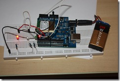
Here is a picture of the Arduino completely disconnected from the computer.  It is being powered by a 9Volt battery and is completely portable.

IMG_9300

Here is a video demonstrating the Arduino + WiShield in action:

By going to the following webpage on any computer in my home network, I am able to control the state of the lights:

image

Before giving you the code and circuit layout, let me tell you a little about the journey to this point.

I saw the WiShield on eBay I saw the LinkSprite CuHead WiFi Shield for Arduino for sale for $55 + $5 shipping.  I thought it would be worth experimenting with.  (As of 7/3/2011 it can still be bought on ebay cgi.ebay.com/ws/eBayISAPI.dll?ViewItem&item=110708459270#ht_2643wt_923)  Here is some critical information from the ebay listing:

This is the shield you need to get Wi-Fi connectivity to your Arduino-based project! This shield provides 802.11b connectivity and is a direct drop-on plug-and-play solution to your Arduino Diecimila/Duemilanove/Uno.

Compatible with Asynclab wifi shield!

Shield Features

  • Add-on shield built for Arduino Diecimila, Duemilanove and Uno
    • Dimensions, shape, even color match exactly!
    • True plug-n-play solution
  • Uses SPI for host communication (max speed 25MHz)
  • All Arduino headers brought out for easy access
  • Easy access reset button on-board
  • On-board PCB antenna
  • Switchable interrupt pin usage between INT0 and digital pin 8
  • Switchable LED on digital pin 9
  • Switchable CS pin for serial flash between digital pin 10 and digital pin 7[1]

Wi-Fi Module Features

  • 802.11b Wi-Fi certified
    • 1Mbps and 2Mbps throughput speeds
  • Supports both infrastructure (BSS) and ad hoc (IBSS) wireless networks
  • Ability to create secured and unsecured networks
    • WEP (64-bit and 128-bit)
    • WPA/WPA2 (TKIP and AES) PSK
  • Low power usage
    • Sleep mode: 250μA
    • Transmit: 230mA
    • Receive: 85mA

Pin Usage

  • SPI
    • Slave select (SS) : Arduino pin 10 (port B, pin 2)
    • Clock (SCK) : Arduino pin 13 (port B, pin 5)
    • Master in, slave out (MISO) : Arduino pin 12 (port B, pin 4)
    • Master out, slave in (MOSI) : Arduino pin 11 (port B, pin 3)
  • Interrupt (Uses only one of the following, depending on jumper setting)
    • INT0 : Arduino pin 2 (port D, pin 2)
    • DIG8 : Arduino pin 8 (port B, pin 0)
  • LED : Arduino pin 9 (port B, pin 1)
    • To regain use of this pin, remove the LED jumper cap
  • 5V power
  • GND

If you setup the serial dataflash CS pin to use pin 10, then the WiFi module will not be usable.  In order to use the dataflash and WiFi concurrently, the dataflash jumper CS pin must be set to pin 7.

Download:

Schematics


Several key things that I should have realized from this listing that would have saved me a lot of time. 

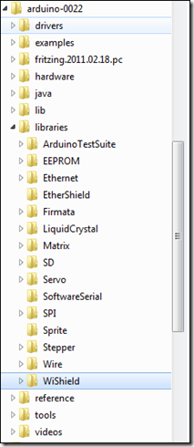
First thing I should have read was “Compatible with Asynclab wifi shield!”  This would have led me to the AsyncLabs Wiki and would have saved me a lot of time.  And it would have led me to download the needed library and example files from the GitHub repository.  Installing these files just required putting them in the “libraries” folder under the “arduino” folder on my PC. 

image 

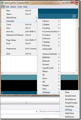
Once I did this, I saw the example sketches (arduino programs) in the IDE:

image

At first none of the examples would work except the “WebServer” example.  Everything else gave me compile errors.  The missing part was this note on asynclabs.com/wiki/index.php?title=WebServer_sketch:

IMPORTANT NOTE:

The WiShield library includes support for both server and client applications. The individual apps are included as sample sketches but to switch between the two will require rebuilding the WiShield library as it requires reconfiguration of some variables. The library is configured as a webserver by default. To switch between modes:

  • Uncomment the appropriate mode, APP_WEBSERVER or APP_WEBCLIENT in the apps-conf.h file in the WiShield directory.

Depending on the mode you want the WiFi module to run, you have to comment out and uncomment out lines in the apps-conf.h file in the WiShield library folder.  It continues with this note:

    • Delete all the object files (files with an extension of ‘.o’) in the WiShield directory.
    • Delete the ‘applet’ directory in the WiShield/examples/WebServer/ or WiShield/examples/WebClient/ directories.
    • Restart the Arduino IDE to rebuild the library in the appropriate mode.

I could not find any “.o” files or “applet” directory to delete.  I did restart the Arudino IDE, but I am not 100% sure this was required.

At the top of all the examples, there is this section of code that you need to configure for your network:

// Wireless configuration parameters —————————————-
unsigned char local_ip[] = {192,168,1,22};    // IP address of WiShield
unsigned char gateway_ip[] = {192,168,1,1};    // router or gateway IP address
unsigned char subnet_mask[] = {255,255,255,0};    // subnet mask for the local network
const prog_char ssid[] PROGMEM = {“ssid"};        // max 32 bytes

unsigned char security_type = 3;    // 0 – open; 1 – WEP; 2 – WPA; 3 – WPA2

// WPA/WPA2 passphrase
const prog_char security_passphrase[] PROGMEM = {"passphrase"};    // max 64 characters

// WEP 128-bit keys
// sample HEX keys
prog_uchar wep_keys[] PROGMEM = { 0x01, 0x02, 0x03, 0x04, 0x05, 0x06, 0x07, 0x08, 0x09, 0x0a, 0x0b, 0x0c, 0x0d,    // Key 0
                  0x00, 0x00, 0x00, 0x00, 0x00, 0x00, 0x00, 0x00, 0x00, 0x00, 0x00, 0x00, 0x00,    // Key 1
                  0x00, 0x00, 0x00, 0x00, 0x00, 0x00, 0x00, 0x00, 0x00, 0x00, 0x00, 0x00, 0x00,    // Key 2
                  0x00, 0x00, 0x00, 0x00, 0x00, 0x00, 0x00, 0x00, 0x00, 0x00, 0x00, 0x00, 0x00    // Key 3
                };

Set the IP address and the default gateway according to your network.  The SSID needs to be replaced with the name of your wifi network.

The “security_type” needs to be set according to your network.  It supports “open”, “WEP”, “WPA”, and “WPA2”.  On my network, I run WPA2, so I set this to “3” as indicated in the comment by this value in the code above.

WPA2 only requires a passphrase, which I put where it says {“passphrase”} above.

Now for the example.  Let’s get the wiring done first.  I hooked up three LEDs each has a 200 ohm resistor and then connected to ground.  The positive pin of the LED I have hooked up to pin 7 for green, pin 6 for white/blue, pin 5 for red.  I originally tried pin 2, but this pin is used by the WiShield and would not work.  (That is the other piece of critical information that I needed from the eBay listing, which pins are being used.)

Now here is the code for the project, (minus all the security information for my network):

/*
* A simple sketch that uses WiServer to serve a web page
*/

#include <WiServer.h>

#define WIRELESS_MODE_INFRA    1
#define WIRELESS_MODE_ADHOC    2

// Wireless configuration parameters —————————————-
unsigned char local_ip[] = {192,168,1,22};    // IP address of WiShield
unsigned char gateway_ip[] = {192,168,1,1};    // router or gateway IP address
unsigned char subnet_mask[] = {255,255,255,0};    // subnet mask for the local network
const prog_char ssid[] PROGMEM = {"ssid"};        // max 32 bytes

unsigned char security_type = 3;    // 0 – open; 1 – WEP; 2 – WPA; 3 – WPA2

// WPA/WPA2 passphrase
const prog_char security_passphrase[] PROGMEM = {"passphrase"};    // max 64 characters

// WEP 128-bit keys
// sample HEX keys
prog_uchar wep_keys[] PROGMEM = { 0x01, 0x02, 0x03, 0x04, 0x05, 0x06, 0x07, 0x08, 0x09, 0x0a, 0x0b, 0x0c, 0x0d,    // Key 0
                  0x00, 0x00, 0x00, 0x00, 0x00, 0x00, 0x00, 0x00, 0x00, 0x00, 0x00, 0x00, 0x00,    // Key 1
                  0x00, 0x00, 0x00, 0x00, 0x00, 0x00, 0x00, 0x00, 0x00, 0x00, 0x00, 0x00, 0x00,    // Key 2
                  0x00, 0x00, 0x00, 0x00, 0x00, 0x00, 0x00, 0x00, 0x00, 0x00, 0x00, 0x00, 0x00    // Key 3
                };

// setup the wireless mode
// infrastructure – connect to AP
// adhoc – connect to another WiFi device
unsigned char wireless_mode = WIRELESS_MODE_INFRA;

unsigned char ssid_len;
unsigned char security_passphrase_len;
// End of wireless configuration parameters —————————————-

int redState = 0;
int whiteState = 0;
int greenState = 0;

int redPin = 5;
int whitePin = 6;
int greenPin = 7;

// This is our page serving function that generates web pages
boolean sendMyPage(char* URL) {
    if (strcmp(URL, "/red") == 0) redState = !redState;
    if (strcmp(URL, "/white") == 0) whiteState = !whiteState;
    if (strcmp(URL, "/green") == 0) greenState = !greenState;
    digitalWrite(redPin, redState);
    digitalWrite(whitePin, whiteState);
    digitalWrite(greenPin, greenState);
    // Check if the requested URL matches "/"
   // if (strcmp(URL, "/") == 0) {
        // Use WiServer’s print and println functions to write out the page content
        WiServer.print("<html>");
        WiServer.print("Light Control<br><br>");
        printLightStatus("red", redState);
        printLightStatus("white", whiteState);
        printLightStatus("green", greenState);
        WiServer.print("The page you requested was: ");
        WiServer.print(URL);
        WiServer.print("<br>The arduino has been running for: ");
        WiServer.print(millis());
        WiServer.print(" milliseconds<br>");
        WiServer.print("</html>");
        // URL was recognized
        return true;
    //}
    // URL not found
    return false;
}

void printLightStatus( String lightName, int lightState) {
  WiServer.print(lightName);
  WiServer.print(" Light is ");
        if(lightState ==0) {
            WiServer.print(" <b>off</b> <a href=/");
            WiServer.print(lightName);
            WiServer.print(">Turn On</a><br>");
        } else {
          WiServer.print(" <b>on</b> <a href=/");
            WiServer.print(lightName);
            WiServer.print(">Turn off</a><br>");
        }
}

void setup() {
  // Initialize WiServer and have it use the sendMyPage function to serve pages
  WiServer.init(sendMyPage);
  // Enable Serial output and ask WiServer to generate log messages (optional)
  Serial.begin(57600);
  WiServer.enableVerboseMode(true);
  pinMode(redPin, OUTPUT);
  pinMode(whitePin, OUTPUT);
  pinMode(greenPin, OUTPUT);
}

void loop(){

  // Run WiServer
  WiServer.server_task();
  delay(10);
}


Several other things to note.  On the board it says “Copperhead WiFi Shield”.  However, on the net, it is referred to only as “CuHead Wifi Shield”.  (Cu being the atomic symbol for Copper.  This was very frustrating, as I could not find any information about the Copperhead Wifi Shield…. Lots of stuff on Copperheads but nothing related to WiFi or Arduinos 🙂 ).  Also, it has the link www.linksprite.com on the board, but I found the AsyncLabs.com to be the place to get my answers.

If you find a cheaper place to get the WiShield, please leave a comment and let me know.  It would open up a whole lot more possibilities if it was possible to get WiFi connectivity in the $20 range. 

Also, if you know some really cool projects using the WiShield, let me know that too.

Arduino Cookbook (part 2) – What was left out and other information from the preface

Let’s continue going through the Arduino Cookbook by Michael Margolis.  (see the first article about the book.)

The book doesn’t cover much electronics theory and practice, but provides some basic guidance.  If you want some more background in this area, then these books are recommended:

• Make: Electronics by Charles Platt (O’Reilly)
• Getting Started in Electronics by Forrest Mims (Master Publishing)
• Physical Computing by Dan O’Sullivan and Tom Igoe (Cengage)
• Practical Electronics for Inventors by Paul Scherz (McGraw-Hill)

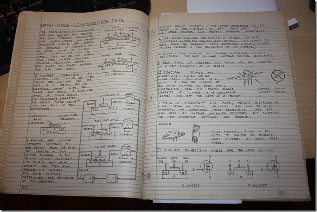
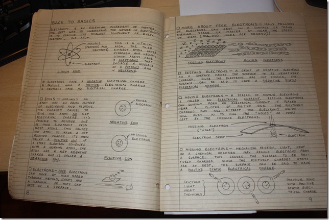
These all look like good books to go through, and we might have future series going through these books.  I recognized the Getting Started in Electronics by Forrest Mims.  I had bought it nearly 25 years ago!!  And I still have that copy.  I was going through it with my children (ages 8 and 12) this summer.  It has some wonderful illustrations in it.  Here are some pictures to give you a sense:

IMG_9283 IMG_9282

The Arduino Cookbook explains code to do very specific things.  The author recommends the following books to give you more information on programming in general and C in particular:

• Practical C Programming by Steve Oualline (O’Reilly)
• A Book on C by Al Kelley and Ira Pohl (Addison-Wesley)

The C Programming Language by Brian W. Kernighan and Dennis M. Ritchie(Prentice Hall)

The code in the Arduino Cookbook has been tested with release versions 0018 through 0020.  It was written before v1.0 was finalized.  There might be small changes required to make the code work, and we are directed to this website:

www.oreilly.com/catalog/9780596802479/

So, if you have doubled checked, and tripled checked something from the book, and it does not work as expected, then check the link above to see if there are some changes required.  There is also an Appendix on troubleshooting, and more help can always be found from: www.arduino.cc

In the section “Using Code Examples” it says:

This book is here to help you make things with Arduino. In general, you may use the code in this book in your programs and documentation. You do not need to contact
us for permission unless you’re reproducing a significant portion of the code. For example, writing a program that uses several chunks of code from this book does not require permission. Selling or distributing a CD-ROM of examples from this book does require permission. Answering a question by citing this book and quoting example code does not require permission. Incorporating a significant amount of example code from this book into your product’s documentation does require permission.

We appreciate, but do not require, attribution. An attribution usually includes the title, author, publisher, and ISBN. For example: “Arduino Cookbook by Michael Margolis
with Nick Weldin (O’Reilly). Copyright 2011 Michael Margolis and Nicholas Weldin, 9780596802479.”

If you feel your use of code examples falls outside fair use or the permission given here, feel free to contact us at permissions@oreilly.com.

In this set of blog posts, I will be going through the book, page by page, but we will not be putting the information in the book on this page.  Instead I will be providing some feedback, additional information, and my own personal experiments related to the information in the book.  Therefore, you will want to get the book in order to make best use of these blog posts.  Please use the link below so that we can get a small commission from Amazon to help support this site and the buying of all the Arduino related materials that we need to keep experimenting:

Arduino Cookbook

If you like online versions of things, then you should check out Safari Books Online:

my.safaribooksonline.com.

This is actually how I am reading the book, free through a service provided by my local library (www.hcpl.net/).  It is a great way to get technical books, that are searchable, without having to find a place to store them.    It can be great when doing some of the examples having the ability to copy and paste from the electronic book to the code editor without having to type it in, or try to find an alternate resource to get it from.

The Acknowledgments section can sometimes be very useful to read.  There are several people that Michael thanks:

Nick Weldin

Simon St. Laurent – editor at O’Reilley

Brian Jepson (twitter)– helped to provide the Xbee content in chapter 14

Audrey Doyle – fixed typos and grammatical errors

Philip Lindsay – chapter 15 help – how to make Ethernet more understandable

Mikal Hart – GPS recipes and software serial

Core Arduino development team: Massimo Banzi, David Cuartielles (twitter), Tom Igoe, Gianluca Martino, and David Mellis

Alexandra Deschamps-Sonsino, CEO of Tinker London (has workshops for the Arduino)

Peter Knight

SparkFun

Maker Store

Gravitech

NKC Electronics

Modern Device

Liquidware

Adafruit

Makerbot Industries

Mindkits

Oomlout

SK Pang

Brock Craft

Daneil Soltis

(families of the writers)

Joshua Nobel for his book Programming Interactivity:  A Designer’s Guide to Processing, Arduino, and Openframeworks (published July 28, 2009)  (This looks like a good book for us to go through too)

In the next post, we will get into Chapter 1 – Getting started…

Arduino Cookbook by Michael Margolis


In order to bring some structure to my experiments with the Arduino, and to help me get through the learning curve quicker, I thought it would be good to have a book to guide me.  The book I have selected is the Arduino Cookbook by Michael Margolis.  It is a recent book, published in March 2011.  The first words of the preface say just what I am looking for.  “This book was written to help you explore the amazing things you can do with Arduino.” Yay

Preface

Arduino is a family of microcontrollers (tiny computers).  It can be used for “physical computing”.  Actually responding to and interacting with the “real world”.

This book is aimed at a broad range of people.  There is no assumption about a particular hardware or software background.  But even if you have a microcontroller background or a background in C/C++, you will still find this book very useful.

What does this book cover?

Chapter 1 – Getting Started – (everything you need to get that first program written, that first circuit created, and possibly even that first LED blinking?)

Chapter 2 – Making the Sketch Do Your Bidding.  (“sketches” are what we call the Arduino program)  This chapter covers the key software concepts and task.

Chapter 3 – Using Mathematical Operators

Chapter 4 – Serial Communications – how to connect to the computer and other devices using a serial connection.

Chapter 5 – Simple Digital and Analog Input – how to actually get the data into the arduino

Chapter 6 – Getting Input from Sensors – enable touch, sound, position, heat, and light

Chapter 7 – Visual Output – controlling LEDS (ok, looks like they wait until this chapter to get that first LED blinking?)  Switch on one or many LEDs, controlling brightness and color.  How to create bar graphs, numeric LED displays, create patterns, animations with LED arrays.

Chapter 8 – Physical output .. how to make things move with solenoids (I’ve never quite understood what a solenoid is…)  servo motors (got some of them floating around… will be good to put them to some good use… found some for sale on eBay for just a few cents too.  but possibly will not win those)  Physical output is where the rubber meets the road.  This is where we make things move!  Can’t wait till we get to chapter 8!!!

Chapter 9 – Audio Output – generate sounds by playing wav files and MIDI output.

Chapter 10 – Remotely Controlling External Devices – interact with the TV, cameras, garage doors, appliances, toys. 

Chapter 11 – Using Displays – interfacing with text and graphical LCD displays

Chapter 12 – Using Time and Dates – measuring time; handling time delays (here we will learn what we need to know to develop a clock, timer, and I could create a speech timer for my toastmaster club…)

Chapter 13 – Communicating using I2C and SPI  (I have did one project in the Parallax Basic stamp book using I2C.  I understand it is a protocol to connect things together.  I am completely unfamiliar with SPI…)

Chapter 14 – Wireless Communication – using XBee

Chapter 15 – Ethernet and Networking – hook up things to the Internet.  (I have been playing around with the EtherShield, and got a web page setup to control a little LED.  But I got the cheaper enc28j60 based EtherShield.  Not the newer, expensive one based on the Wiznet chip.  The API calls for the Enc28j60 are a lot more difficult to understand than the newer ones.  The difference in cost though is about 100%.  You can get the Enc28j60 etherShield for about $20.  The Wiznet one will be around $45.  It will be interesting to see which one the book uses… I think we can both already guess 🙂 )

Chapter 16 – Using, Modifying and Creating Libraries (maybe this is where I can learn how to create a easier to use library wrapper for the EtherShield that I have. )

Chapter 17 – Advanced Coding and Memory Handling

Chapter 18 – Using the Controller Chip Hardware – How to access and use hardware functions that are not “fully” exposed through the documented Arduino language… (Sounds interesting and advanced)

I have no idea how long it will take to get through the book.  And I imagine we will be taking a lot of detours on the way to create projects using what we have learned.  But I would recommend that if you are starting with the Arduino that you get the book and come along this journey with me.  I intend to keep you updated on my progress in the book, and I intend to publish the code and projects that I create from the things that I learn from the book, but to fully understand everything, you will need the book.  Please use this link:

Also, if you live in Harris county, then you can access it through the Harris Public County Library who has an arrangement with SafariBooksOnline to make it available.  Your library might have a similar setup.

Follow Me Game – Arduino Based Game

Remember playing MySimon (Simon Says) back in the 1980s?  It was a simple game that could entertain you for hours.  It had 4 buttons, each of a different color.  Turn on the game, and one of the buttons would glow.  Then you had to press that button.  Another button was added to the pattern, and the goal was to get to the longest pattern without messing up.
Here I show a simple Arduino based version of this game.  It is simpler because there are only 3 buttons, but it is completely open for you to build on and learn from.


image

See the circuit and files on Fritzing.org


Update:  I received an email about a more sophisticated version of Simon.


Arduino SimonGame

More infos at jadiema.blogspot.com/
Arduino Simon Game: Version 3
Initial Release from David M. Auld (19th October 2009): Version 1 & 2
www.dave-auld.net/index.php?option=com_content&view=article&id=96:arduino-project-simon-game&catid=54:arduino-projects&Itemid=107
Added some features by jadiema: Version 3:
NEW: Added EEPROM storage for high score: level and name
NEW: Multilangage selection
You’ll find the code at: code.google.com/p/my-arduino-projects/downloads/detail?name=Arduino_SimonGame_EEPROM_LANGUE_V3_1.pde&can=2&q=#makechanges

Simple Scoreboard using the Arduino processor

The Arduino microcontroller board has got to be one of the coolest things to come along.  If you ever wanted to create simple gadgets and devices without that much hassle, then this the board to get.  You can hook it up to your computer using the USB port, program in a simple C language, download the code, and away you go.  You can use it to create controllers for your games, lights for your Christomas tree, loggers for your garden, monitors for your rooms, and controllers for your robots.  All you need is a little patience and imagination (access to Google helps too 🙂 ).

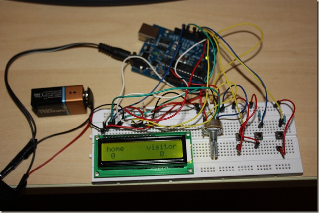
Today, I want to share with you a little project that we created.  It is a simple scoreboard.  It took us about 20 minutes to put together, but that is because we were just learning and didn’t know much. 

We started out by finding this example on how the LCD panel works: www.arduino.cc/en/Tutorial/LiquidCrystal 

Then we hooked up some buttons, added some variables, created several iterations between our code.

Start off displaying the “Hello World” message in the LCD example.  Then had added a “homeScore” variable and displayed that.  Then added the Home Button.  And tested to see if it was “high”, i.e. “on” in our code.  Our first version of the code did not have the “delay” commands, and pressing the button one time caused the score to increment by 50-120 points.  This was because the loop would have that many cycles before the button was brought back “low”, i.e. “off”.  Adding the “delay” kept this from happening.  Then did the same thing for the visitor button.  Required some experimentation with the lcd.SetCursor command to get the visitor scores to show up in the right place.  Then added the reset button and set the scores to 0 when it was pressed.  Ran into the problem that if the score had become two digit, then the 0 was only over writing part of the digits.  Decided to “clear” the display completely on reset, which resolved the problem.  Then cleaned up the code a little, and this was the results:


IMG_8725

image

Code (based on LCD example: www.arduino.cc/en/Tutorial/LiquidCrystal )

/*
Simple Scoreboard

Shows a simple Home/Visitor scoreboard

*/

// include the library code:
#include <LiquidCrystal.h>

// initialize the library with the numbers of the interface pins
LiquidCrystal lcd(12, 11, 5, 4, 3, 2);

int homeScore;
int visitorScore;
const int buttonHomePin = 6;
const int buttonVisitorPin = 7;
const int buttonResetPin = 8;
int buttonState = 0;

void setup() {
  // set up the LCD’s number of columns and rows:
  lcd.begin(16, 2);
  // Print a message to the LCD.
  setupScreen(); 
}

void setupScreen()
{
  lcd.clear();
  lcd.setCursor(0,0);
  lcd.print("home     visitor");
  homeScore = 0;
  visitorScore = 0;
}

void loop() {
  buttonState = digitalRead(buttonHomePin);
  if(buttonState == HIGH)
  {
    homeScore++;
    delay(500);
  }
    buttonState = digitalRead(buttonVisitorPin);
  if(buttonState == HIGH)
  {
    visitorScore++;
    delay(500);
  }

   buttonState = digitalRead(buttonResetPin);
  if(buttonState == HIGH)
  {
    setupScreen();
  }
   lcd.print(homeScore);
   lcd.setCursor(12, 1);
   lcd.print(visitorScore);
}